


 3:35 AM
 RIPON COMPUTERS


 Hardware Networking:-

Hardware Networking:-
By Chris Brenton
Chapter 15 from Multiprotocol Network Design and Troubleshooting, published by Sybex, Inc.
As we discuss these devices, I will cover the pros and cons of each and give examples of its intended use.
These days there is a multitude of networking products to consider when planning your network infrastructure. There are devices for everything from connecting computer systems to the network, to extending a topology's specifications, to controlling network traffic. Sometimes your choices are limited. For example, to connect an office computer to the network, you must have a network card.
Some products, however, require extensive planning prior to selection. For example, should you buy a bridge, a switch, or a router to control network traffic? Not knowing the right answer to this question could lead to a purchase based on your hardware vendor's recommendations. This recommendation may or may not be the best choice, as the vendor may not understand your environment as well as you think. None of these devices are one-size-fits-all. If a consultant is willing to give you design recommendations based on a five-minute phone call, then find another consultant. Each device has been designed with a specific purpose in mind. The trick is to ensure that this purpose is a correct match for the way you use your network.
In this chapter we will define some of the common hardware used in building a network. The only mandatory hardware is a network card (for connecting each computer to the network cable), and, if you will be running twisted-pair cable or Fiber Distributed Data Interface (FDDI) in a star topology, you will require a hub. From here, simply add cables and computers until you have a fully functional network.
The rest of the devices outlined in this chapter are used for providing additional functionality. For example, you do not need to use punch-down panels, but they can greatly simplify wire management of a large network. You do not need to use repeaters or switches, but they can be effective means of extending the distances your network will cover or controlling traffic.
As we discuss these devices, I will cover the pros and cons of each and give examples of its intended use.
On This Page
Punch-Down Panels
Use a punch-down panel to connect hardware located in wiring closets or server rooms to the cabling that runs out to the users' workstations. A punch-down panel is a panel the width of a network rack (a rack with a 19"-wide frame used to hold networking equipment) and contains female RJ-45, RJ-11 (for twisted-pair), or SMA (for fiber) connectors in the front and punch-down blocks in the back. Panels with RJ-11 connectors are typically used for phone connections, while RJ-45 is used with networking. Check the ANSI/EIA category standards (listed in Chapter 2) to see what level of bandwidth a particular punch-down panel supports. While CAT 3 is sufficient for phone use, you will usually want CAT 5 for any panels used to support network communications.
Punching Down the Wire
The punch-down blocks on a twisted-pair panel (CAT 3 or CAT 5) for data use a set of eight bare metal teeth which consist of two blades each. The separation between the two blades is such that a single wire from a standard twisted-pair cable can be pushed in between them and the cable insulation will be cut back, allowing the blades to make an electrical connection with the conductor.
Note: The act of connecting a cable is referred to as punching down the wire. While fiber does not use metal teeth (it's a standard buffed and polished fiber connection), the term is still used for consistency.
Punch-down panels are extremely useful for keeping your wiring organized. Typically these panels are wall or rack mounted. The punched-down wire will lead back to a wall connector in an office area or to another central wiring point. This allows you to plug a cable into the front connector on the panel and either connect the drop to a device (like a hub) within the room or route it to another drop area.
Note: A drop is a wire run from one geographical location to another.
Using punch-down panels is greatly preferred over simply putting a connector on the wiring room side of the drop cable, as it increases the flexibility of the wiring plan. A cable with a connector on the end cannot be as easily rerouted to another drop area and it cannot be lengthened if you need to move equipment around the room.
Warning: You cannot extend a twisted-pair cable by splicing in more wire with the old twist and tape method. Don't even think about it. Spliced cable is too susceptible to signal loss and outside noise. If you need a longer cable, you must replace the entire length.
Things to Consider
Consider the following items when deciding to use a punch-down panel:
- Use a punch-down panel that supports your wiring specification. For example, do not use a CAT 3 punch-down panel with CAT 5 cable. The result is a network that only meets CAT 3 specification.
- Choose the location of your punch-down panel wisely. Once it's in place it can be a real bear to move.
- Ensure that wherever you locate the punch-down panel there is some means of supporting the weight of all the cables that will be running to it (both in the front and in the back). It always helps to think big and plan on having two or three times as many wires as you think you will ever need. While you may initially be wiring only a few drops, this number can grow quickly. Wire runs that hang or droop prior to being punched down will cause stress on the punch-down block. It's not uncommon for wires to pull themselves loose in these situations. Use a wiring ladder or fasteners to carry the weight of the wires.
- Label your network drops on the front of the panel. Someday you will have a problem that can only be resolved by tracing the cables. If drops are not labeled you're in for a long night. A label can simply be some form of unique alphanumeric identifier that indicates where the cable drop goes. Make sure you label the wall plate on the other end with this same identifier.
Labeling Schemes
I've run across many labeling schemes and found one in particular that seemed to be pretty efficient. The label identifies the punch-down location of the user's network drop. It has six characters but can be modified for smaller environments. Wire drops are labeled as follows:
- with a number indicating to which floor the drop connects
- with a letter indicating to which wire or server room the drop connects
- with a number indicating to which rack the drop connects
- with a letter indicating to which patch panel on the rack the drop connects
- with a number indicating to which connector on the panel the drop connects
Let's say a user calls the help desk line and states that they cannot connect to the network. After questioning them you feel that their system may be okay, but you want to check their network connection. You ask them to read the label on their network wall plate and they reply, "4A3B23." You now know you need to go to the 4th floor, Room A. Within the room this user's network drop is wired to the 3rd rack on the patch panel labeled B. Their connection would be number 23 on that panel. For smaller environments you could simply drop the floor and room identifiers. Figure 4.1 shows a set of patch panels mounted in a standard network rack.

Figure 4.1: A set of patch panels mounted in a standard network rack
Most of the other numbering systems I've seen require you to look up the user's location in some form of matrix and cross reference this information to find the drop's location. This can be a pain if the user catches you in the hall or in some other location where you cannot quickly access this information
Network Interface Card
A network interface card (NIC) is used to connect a computer to the network. It includes two interfaces—one to connect to the network and one to connect to the computer itself. The NIC is the brains of the network connection, containing its own processor chip to help take some of the load off the computer's central processing unit (CPU). The more efficient the NIC card's circuitry, the less of a load it will place on the system. While this is not a big deal on a workstation, it can kill a server if it contains multiple NICs. When choosing a server network card, make sure you stick with a vendor who is known to produce high-performance cards.
There are a number of different varieties of NIC cards. The first thing to look at is how the card interfaces with the computer. There are three types of NIC card interfaces:
- attaching to an external port on the computer such as the parallel port
- installed internally in a Peripheral Component Interconnect Mezzanine/Computer Interface Adapter (PCIM/CIA) slot, now known simply as a PC slot
- installed internally within the system connecting directly to the computer bus
External Port Connection
An external port interface is probably the easiest to use but yields the poorest performance. An external port is typically an oval-shaped device that fits in the palm of your hand. On one side is a male 25-pin connector that attaches directly to the parallel port of the computer. This is why these network cards are commonly referred to as parallel port network cards.
On the other side is a 10BT, a coaxial connector, or both for connecting to the network. Most of these devices also require power and need to be plugged into an AC outlet or the PS/2 port of the computer. The software drivers used are identical to your standard network card drivers except they direct all network traffic through the parallel port. If you use one of these cards you lose the use of the parallel port for local printing (although you can still print to a network printer). Figure 4.2 shows a parallel port network adaptor card.
The benefit of a parallel port connection is ease of use. It was originally intended to connect laptop systems which did not have a bus or PC slot available. If you have an older laptop this may be your only means of connecting it to a network.
The downside to external ports is that their performance is poor. Because everything runs through the parallel port, these network cards saturate at about 1,300 frames per second (fps). Still, this may be ample for someone who is looking to simply share a few files or print. The other drawback is that supported topologies are usually limited to 10 Mb Ethernet. Don't expect to see expanded support for these devices, due to their poor performance and the popularity of PC cards. One final thing to be sure of is that the parallel port supports bi-directional communications. A standard parallel port only supports one-way (outbound) communications—as it was designed to send data to a printer without expecting a reply back. While bi-directional parallel ports are pretty common these days, the older systems that could benefit most from this type of network connection are the ones that were outfitted with the standard ports.

Figure 4.2: A parallel port network adapter card. The knobs on each side of the unit attach it securely to the parallel port.
PC Card Connection
PC card connections are pretty common these days and are typically used for connecting a laptop to a network. These cards are about the size of a credit card and only three or four times thicker. The card slides into a PC card slot on the computer and usually has some type of special cable that allows the card to connect to standard network wiring.
The upside to PC cards is increased performance. The average user will not notice a performance difference between a PC slot network card and one that plugs directly into the bus. A PC card is the preferred method of connecting a laptop to a network when possible.
One major drawback of PC cards is configuration. If you're using a plug-and-play computer and operating system, then set-up is usually pretty easy (it's almost plug-and-play). If you are using a non plug-and-play operating system like DOS, then the configuration can be a real nightmare for even a seasoned PC support specialist. Most such systems require about a half dozen drivers to be loaded prior to loading the network drivers. Even if you are successful in configuring the system and are able to log in to the network, there is no guarantee you will still have enough conventional memory left on your system to actually run any of your programs. Figure 4.3 shows a PCIM/CIA or PC card network adapter. Note the special cable used to connect this card to a standard RJ-45 connector.

Figure 4.3: A PCIM/CIA or PC card network adapter
Internal Network Card Connection
Internal network cards are by far the most popular variety of connection. They are internal cards that plug directly into the computer's bus through installation to a free expansion slot in the back of the system, as shown in Figure 4.4. The circuit board plug at the bottom of the card plugs into the expansion slot of the computer.

Figure 4.4: A standard internal network card
Warning: Make sure you use a card that supports the computer's bus type!
Internal network cards support the largest diversity of network topologies. There are vendors making internal network cards for every topology we cover in this book. One important consideration is to determine what kind of bus your computer uses. The most common are:
ISA (Industry Standard Architecture) Developed in 1979 for the IBM XT and implemented in all PC compatible systems to date, ISA is the slowest bus architecture available for the PC, typically running at only 8 megahertz (MHz). This is fine, however, for a low-end workstation connecting to a 10 Mbps network to do simple file and printer sharing. The average ISA NIC can push a 10 Mb network to about a 35% utilization rate if it is tuned properly. While there are 100 Mbps ISA cards available, their performance is pretty dismal. The bus is just too slow to take advantage of the additional bandwidth that 100 Mbps provides. This is definitely not the bus to use in a server!
EISA (Extended Industry Standard Architecture) Developed in 1987 to provide 32-bit throughput using the standard ISA architecture, this is the next generation to the ISA bus. Because EISA can easily keep up with wire speed traffic (100% utilization) on a 10 Mb network, it makes a good fit for server class machines. When the bandwidth jumps to 100 Mb, however, they have trouble keeping up. While there are some decent 100 Mb cards available, they are best limited to workstation use only at these speeds. Keep in mind that your server needs to process information from multiple network clients. Therefore it is always a good idea to maintain it as the fastest system on the network.
Micro Channel Developed in 1987 to provide a proprietary 32-bit alternative to ISA, this was IBM's next generation to the ISA bus. Performance is on par with EISA but the fact that it is only supported by IBM makes for a minimal number of card options.
NU-Bus Developed by Texas Instruments in 1984, this architecture relies on one proprietary processor slot, the Processor Direct Slot. This is legacy bus architecture used by Apple for the Macintosh computers. Most new Macs include PCI bus slots as well.
VESA Bus The Video Electronics Standards Association standard is an enhanced EISA design that provides a dedicated 32-bit line directly from the Vesa slot to the processor. This is known as local bus technology and is ten times faster than ISA.
S-Bus This is SUN's bus architecture for the SPARC station.
PCI (Peripheral Component Interconnect) Developed by Intel, this is now the bus architecture of choice and certainly the fastest of the bunch. To top it off, it is also cheaper to implement than all of the buses listed above with the exception of ISA. Most newer PC systems will contain a minimum of two PCI slots with the rest being made up of some other architecture. PCI has not only found its way into PC compatibles but into Macs as well. All 100 Mbps and faster cards should use a free PCI slot when possible. If the server's PCI slots are at a premium, you may want to check out some of the multi-port cards that have hit the market. These are specifically designed for servers that need to connect to more than one network segment. Each card contains two or four RJ-45 connections.
In the old days workstations used ISA NICs and servers used EISA. Because the server had the faster bus, it was in a better position to handle data requests from multiple clients. The result was a built-in check valve to control the flow of network traffic. Life was good and traffic flowed smoothly.
PCI has brought an interesting spin to network design. Because it is so inexpensive, it is also widely implemented, finding its way into both server and workstation class machines. This means that many of the new workstations are able to crank out data just as fast as the server (maybe even more so if the server has not been upgraded to PCI over the last few years). The result is that the server's NIC card is pushed into saturation, receiving more traffic than it can handle. While this is rare on 10 Mbps networks it can be quite common when speeds are pushed up to 100 Mbps. PCI is currently the fastest thing around, but it still has trouble with a 100 Mbps or more network pushed to full speed. This needs to be taken under careful consideration when you are planning network upgrades. I've seen servers that have run stable for months roll over and play dead when upgraded to 100 Mbps pipes, because the bus has become saturated from the increase in traffic it receives.
Topology and Wiring Support
The final consideration in choosing a network card is to ensure it supports the topology and the wiring you are using. If your topology is 100VG-ANYLAN, then you need a 100VG card. A 100 Mb Ethernet card will not work. Many vendors are now shipping cards that support multiple topologies. If you are currently running 10 Mb Ethernet but have your eye on 100 Mb Ethernet for the future you can purchase 10/100 cards that support both topologies. The card will work in your current environment and be ready for when you upgrade later. Most of these include an auto sensing feature which will detect what network speed you are running at. This is a great feature in that when the upgrade does take place, you will not have to configure any of the workstations; simply power cycle them and they will connect at the faster speed.
Also ensure the NIC's connector is correct for your cabling. If you are using Thinnet, the card should have a BNC connector, for twisted pair, an RJ-45. While media converters are available to connect dissimilar media types, it is always a good idea to limit the number of connectors used. An excessive number of connectors can introduce noise or signal loss to the circuit. Many vendors have had multi-port cards (referred to as combo cards) available for a number of years, and these will connect to a variety of media types. They contain an RJ-45, a BNC, and an AUI (Attachment Unit Interface) connector. An AUI connector is a type of generic connection that requires that a transceiver be used to connect to your cabling. A transceiver is a type of media converter that allows you to attach the network card to any type of cabling that your topology allows. Figure 4.5 shows two transceivers.

Figure 4.5: A transeiver—these devices connect a generic networking port called an AUI to any type of cable media supported by the device.
Media Converters
Media converters are devices used to connect two dissimilar cable types. They are usually palm-size boxes with mating connectors on either end. Converts are available to connect together twisted pair, coax, and fiber in any possible combination. Depending on the application, they may or may not require an external power source.
While it is not always practical to upgrade all network devices when a media change occurs, media converters can be lifesavers in a pinch.
Saved by a Media Converter
I was upgrading an operations center from thinnet to twisted-pair. The center contained a good mixture of Banyan Vines, NetWare, SUN, and Lotus Notes systems. In the process of the upgrade we discovered that a NetWare 2.2 and two Banyan 4.0 servers did not have combo cards like we thought. The network cards were of an unknown vendor and contained only a BNC connector. All three systems were scheduled to be replaced over the next few months but were currently critical to the company's day-to-day operations. Rather than scheduling additional downtime to replace the network cards and taking the chance that these dinosaurs might never come back up again, we installed a media converter instead.
The systems were connected together with a short run of thinnet cable. We terminated and grounded one end and on the other installed a media converter. The media converter was then connected to a twisted-pair cable which in turn connected to our brand new switch (more on switches later).
The result? The systems were back online and functional and we avoided dedicating another Sunday or more to the project.
When using a media converter you must pay close attention to the maximum distances of your cables. Keep the combined distance to the smallest specification of the two cables to avoid difficulty. For example, given the above situation you would want to keep your cable distance to 325 feet, because this is the requirement for twisted-pair cabling. A converter introduces latency, so it is a good idea to stay well below the maximum.
Note: Latency is the delay incurred on a circuit when the signal must undergo processing.
The act of amplifying the signal takes a small amount of time, which can be measured as the time from when the repeater receives the signal to when it transmits it on its other port. If too much latency is added to a network, connections may time out prematurely. We'll discuss this further when we cover troubleshooting later in the book.
Repeaters
Repeaters are simple two-port signal amplifiers. They are used in a bus topology to extend the maximum distance that can be spanned on a cable run. The strength of the signal is boosted as it travels down the wire. A repeater will receive a digital signal on one of its ports, amplify it, and transmit it out the other side.
A repeater is like a typical home stereo amplifier. The amp takes the signal it receives from the CD, tape deck, etc., and amplifies the signal and sends it on its way to the speakers. If the signal is a brand new Alanis Morisett CD, it simply boosts the signal and sends it on its way. If it's an old Grateful Dead concert tape that is inaudible from the amount of background hiss, it happily boosts this signal as well and sends it on its way.
Repeaters function similar to stereo amplifiers. They simply boost whatever they receive and send it on its way. Unfortunately the signal they receive could be a good frame of data, a bad frame of data, or even background noise. A repeater does not discern data quality; it simply looks at each of the individual digital pulses and amplifies them.
Why Use a Repeater?
A repeater is a cheap, effective way of extending your cable lengths. For example, the maximum allowable distance for thinnet cable is 600 feet. By using a repeater, this distance can be extended to 1,200 feet. By using multiple repeaters this distance can continue to be extended until the maximum overall length specification of the topology is reached. For example 10 Mb Ethernet is 3000 feet, so no more than five thinnet repeaters could be used.
A repeater does not follow Ethernet's CSMA/CD rules of listening before transmitting. If another station is partially through a frame transmission, a repeater will blindly transmit as well, causing a collision. This is why the overall maximum topology length must still be adhered to with a repeater. Stations at either end still need to be able to monitor the entire length of the network correctly, prior to transmission.
Choosing a Repeater
When choosing a repeater, ensure that it has transmit and jam lights for each of its ports. These lights are LED indicators that monitor the repeater's operation. The transmit lights let you know when traffic is detected on each of the ports. The jam lights let you know if a collision or a cable problem occurs along an individual length of cable. If a jam light blinks quickly, then two frames have collided. If the light turns on solid, then you probably have a failure somewhere along the length of cable. These indicators can be invaluable troubleshooting tools when you are trying to diagnose a connectivity problem. Figure 4.6 shows a common network repeater. The front indicator lights quickly verify the operation of the device.
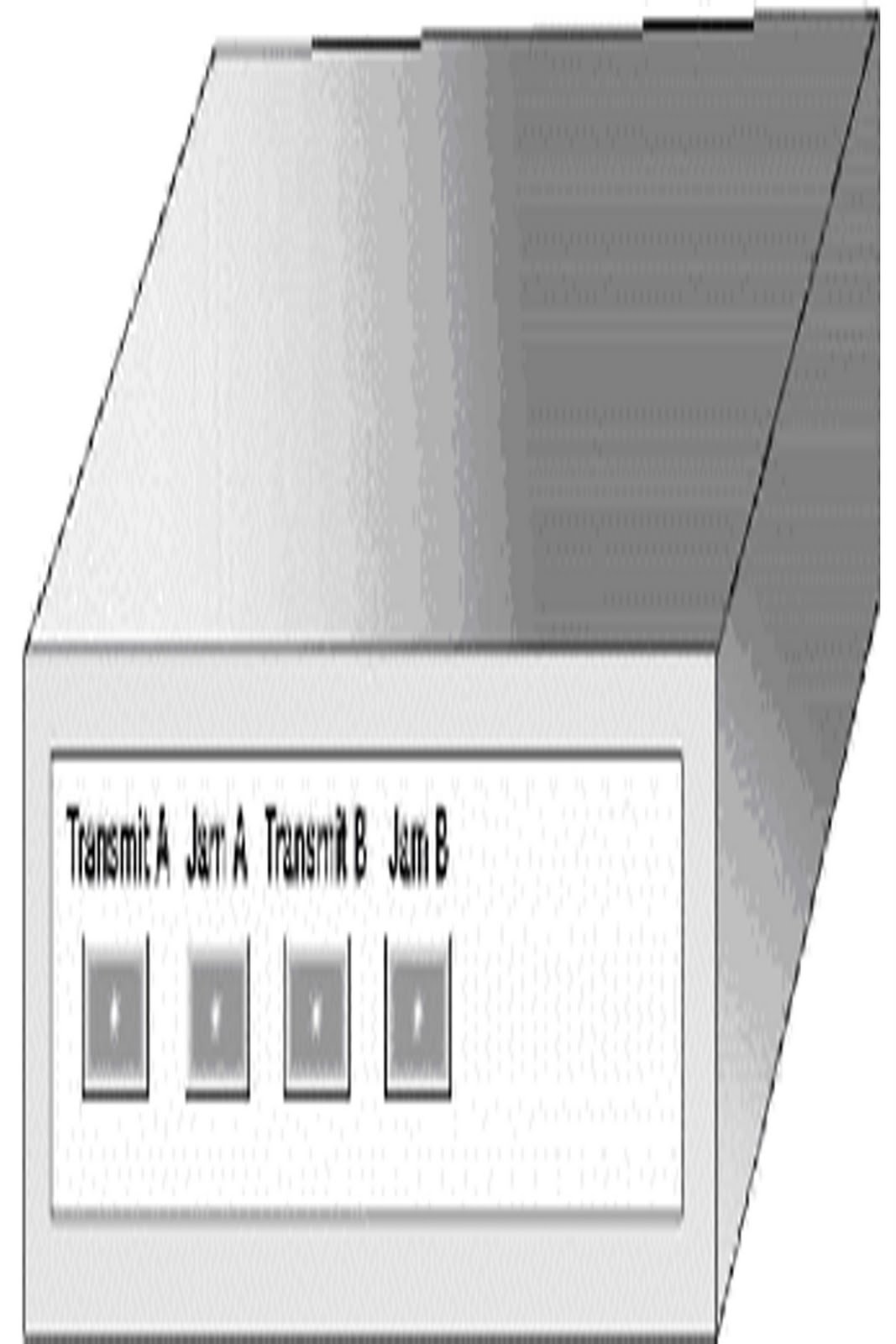
Figure 4.6: A common network repeater
Hubs
Hubs are probably the most common piece of network hardware after network interface cards. Physically, they are boxes of varying sizes that have multiple female RJ-45 connectors. Each connector is designed to accept one twisted-pair cable outfitted with a male RJ-45 connector. This twisted-pair cable is then used to connect a single server or workstation to the hub.
Hubs are essentially multi-port repeaters that support twisted-pair cables in a star typology. Each node communicates with the hub, which in turn amplifies the signal and transmits it on its remaining ports. As with a repeater, hubs work at the electrical level. Because hubs have no way to determine if a frame is good or bad, they should be looked at, when you design your network typology, as functionally identical to repeaters.
Chassis Hubs
Hubs come in two categories, chassis and stackable. A chassis hub is a large box (typically one or two feet tall and the width of a network rack) that is made to mount into a network rack. The chassis has slots similar to (but not the same as) the expansion card slots in the back of a standard PC. These are usually designed so that a card can slide directly in from the front without disassembling the device. On the front of the card are multiple RJ-45 connectors. The number of stations a hub can supported depends on the port density of each card and how many cards are installed. Cards typically support anywhere from four to 24 connections. The number of cards supported by the chassis varies from model to model. Typically, one slot is lost to some form of management card that is used to configure and monitor the remaining cards. Besides hub cards, a chassis hub may also support cards that supply bridge, switch, or even routing functionality.
The appeal of a chassis hub is that it is compact. There are chassis hubs that will support 200 or more connections. If you have a large number of users to support but do not have a lot of room for networking equipment, a chassis hub may be your best bet. Also alluring is the chassis hub's ability to monitor all these ports through a single point of management. A chassis hub management card will usually allow you to monitor every port, allowing you to determine which ones are in use.
Unfortunately, chassis hubs also have many drawbacks, the first of which is a single point of failure. If you support 150 users through a single chassis hub and it goes down, your entire network is offline. Another drawback is that many of the denser hub cards do away with the RJ-45 connectors and use a single proprietary connector with separate twisted-pair cables attached to it. This is the only way to fit 24 or more connections onto a single card; this increases the number of connections a single card can handle, but it can make it difficult to trace wires. While you will be able to determine which card the drop connects to, you may be hard pressed to determine which of the card's ports it is using. Also, if one cable is just a wee bit too short, you cannot just replace it with a standard twisted-pair patch cord. You will need to replace the entire assembly with a longer proprietary unit, if one is even available. These longer units are proprietary in that they do not use connectors commonly deployed with network wiring, so they must be specially made and are not considered an off-the-shelf item like a standard twisted-pair patch cord, which is available from most computer stores and mail order catalogs.
Another major drawback of chassis hubs is the lack of indicator lights. LEDs that indicate port status are removed in order to connect more users. Link status and transmit indicators for each port on a hub are convenient visual aids in trying to diagnose a problem. The link status light will come on when a system is connected and correctly wired to the hub port. The transmit light will flash whenever that station sends data. While most chassis hubs have the ability to monitor a port's health through some form of management software, the loss of visual indicators can greatly inhibit the troubleshooting process.
Chassis hubs are also not very flexible. If I fill a 200-port chassis hub, I may end up with so much traffic on my network that end users constantly complain about poor network performance. While most vendors will sell you an optional card to segment the chassis into multiple virtual hubs, you can usually only create three or four of them. Again, with 200 users I would still have 50 or more people contending for bandwidth. In a busy environment this can still be grossly inadequate. While the argument can be made to refrain from putting so many users on a single chassis hub, doing so would limit a chassis hub's greatest appeal, which is that it supports many users within a small enclosure.
As if all this was not enough, chassis hubs also tend to cost more than their stackable counterpart. With management and segmentation modules the per-port cost can easily be two to three times or more than what you would pay for the equivalent number of ports using stackable hubs.
Stackable Hubs
Stackable hubs are slim line boxes which usually contain between six and 24 ports. Most have link and transmit lights to help monitor the health of each port. Stackables are so named because, as your port requirements grow, you can simply buy another hub and stack it on top of the first. Stackables can also be rack mounted or flush mounted to a wall.
Stackables have a lot going for them, which has made them the hub of choice. The first is cost. If you have a small network, purchase a cheap six-port hub and you're off and networking. As your needs grow you can purchase larger hubs or link smaller ones together.
One of the nice things about stackables is that, if you are using more than one, you do not have a central point of failure. If a hub fails, you can simply move your important users (your boss, his boss, the secretary that brings you cookies every day, and so on) to the hub that is still functioning until a replacement can be found. Note that you can usually mix and match stackable hubs from different vendors, so in a real pinch you may be able to run down to your local computer store and purchase a replacement.
Note: The mix-and-match nature of stackable hubs is in contrast to chassis hubs, which are proprietary, meaning replacements can usually only be purchased through the manufacturer or one of their value added resellers.
Managed Stackable Hubs
Stackables come in two varieties, managed and unmanaged. A managed hub (sometimes referred to as an intelligent hub) runs some form of software that allows you to communicate with the device (either over the network or from a directly attached terminal) and check operating parameters like port status (up or down). This communication is useful if you have an extremely large environment and it is impractical to walk over to the hub and check the indicator lights.
Note: This capacity to check operating parameters is identical to what you get with a chassis hub. Some vendors are even including backbone connectors that allow you to connect multiple hubs together and manage them as if they were one device.
It is also possible to have an intelligent hub send out alerts to a management station, however this may not be as useful as it sounds because these alerts are limited to when the hub has been rebooted or if a port goes down. Personally I would be less concerned with rebooting and more concerned with it going offline initially. Unfortunately, an offline hub has no way of sending an alert. Also, a port will technically go down every time a user shuts off their workstation. Clearly, intelligent hubs are not quite as clever as their name implies. Their useful application is tailored to very specific environments. Unless you know that you will definitely use additional functionality, they may not be worth the additional cost.
Unmanaged Stackable Hubs
An unmanaged hub does not have any type of management or monitoring software. The only indication of their status is the supplied LEDs. I have seen hubs that have locked up, and even though they appear operational at first glance they will not transmit any data. In such a case, the online LED will be lit as will be the link lights for each of the attached stations. If you watch the transmit lights, however, you will see no activity. It is clearly important to only use hubs with indicator lights. One other LED to look for is a collision indicator. Because a hub is a dumb amplifier, it only needs a single collision light for all of its ports. A collision light can be an early warning signal that something is not right with the network. If this light is turned on solid, it's time to break out a network analyzer and find out what is going on.
Backbone Connection
Stackable hubs have two different methods of being connected together—through a backbone connection (if one is supplied) or through an uplink port. A backbone connection is a separate connector designed to be attached to hubs; it is usually implemented as a BNC connector in 10 Mbps hubs and connects the hubs with a short run of thinnet cable.
Note: Some vendors use a proprietary cable to connect their hubs together for management purposes. In this case, these cables will supply the required network connection between the hubs as well.
Uplink Port Connection
An uplink port is a special port that reverses the transmit-and-receive pair of a twisted-pair cable. An uplink port can look like any other hub port, so you should be careful not to use it inadvertently. An uplink port is required because if you directly wire two hubs together the wire pairs will be connected transmit-to-transmit and receive-to-receive; wired this way the hubs will be unable to communicate with each other. Some uplink ports will have a switch next to them to allow you to select their mode of operation. If you have a small network and do not need to connect your hub to another, you can usually throw the switch and use it to connect an extra workstation. Note that only one hub needs to be uplinked. If you use the uplink port on both sides, the hubs will still be unable to communicate.
Tip If you need to connect two hubs together and neither one has an uplink port, you can connect them together with a cross cable. A cross cable is a twisted-pair wire that has the transmit-and-receive pairs switched at one end; this provides the same functionality as an uplink port. Make sure cross cables are labeled as such so they are not confused with regular cables.
Note: The hub can have its RJ-45 connectors on either the front or the back of the unit. Select a unit that fits your wiring scheme. For example, if the hub will be rack mounted it may make more sense to purchase a hub with the connectors in the back. This cuts down on cable clutter, giving the front of the rack a cleaner look.
Figure 4.7 shows three stackable hubs of various port densities. Note the lack of front indicator lights.

Figure 4.7: Three stackable hubs of various port densities
Bridges
A bridge looks a lot like a repeater; it is a small box with two network connectors that attach to two separate portions of the network. A bridge incorporates the functionality of a repeater (signal amplification), but it actually looks at the frames of data, which is a great benefit. A common bridge is nearly identical to a repeater except for the indicator lights, as shown in Figure 4.8. A forward light flashes whenever the bridge needs to pass traffic from one collision domain to another.

Figure 4.8: A common bridge
In our discussion of Ethernet in the last chapter we introduced the concept of a data frame and described the information contained within the frame header. Bridges put this header information to use by monitoring the source and destination MAC address on each frame of data. By monitoring the source address the bridge will learn where all the network systems are located. It will construct a table listing which MAC addresses are directly accessible by each of its ports. It will then use that information to play traffic cop and regulate the flow of data on the network. Let's look at an example.
A Bridge Example
Given the network in Figure 4.9, Betty needs to send data to the server Thoth. Because everyone on the network is required to monitor the network, Betty first listens for the transmissions of other stations. If the wire is free, Betty will then transmit a frame of data. Our bridge is also watching for traffic and will look at the source address in the header of Betty's frame. Because it is unsure of which port the system with MAC address 00C08BBE0052 (Thoth) is connected to, it amplifies the signal and retransmits it out port B. Note that up until now the bridge functionality is very similar to that of a repeater. The bridge does a little extra, however; it has learned that Betty is attached to port A and creates a table entry with her MAC address.

Figure 4.23: Another potential design for our advertising network
This option may be more desirable because it can be supported by a switch with a minimal number of ports and thus reduce the cost. It also reduces the maintenance requirements, as we did not need to create any VLANs.
Note: This option would not be able to help with our protocol broadcast issue.
With Three NT Servers
Our final example network would benefit in much the same way. If we gave each of the three NT servers their own port and cascaded hubs off of the switch for the user community, we would strike the best balance between cost and performance. A switch would cost a bit more than the bridge solution we discussed earlier, but it would allow for greater flexibility. When bridging the network, each collision domain consisted of 50 users each. There was no easy way to segment the users even further. With a switch, we could simply cascade an additional hub off of a free hub port and migrate some of the users over to it. Because only a single protocol is in use, we are not concerned with isolating broadcast frames as we were in the last example.
Routers
A router is a multi-port device that makes decisions on how to handle a frame, based on protocol and network address. To truly understand what this means we must first look at what a protocol is and how it works.
Up until now we've been happily communicating using the media access control address assigned to our networking devices. Our systems have used this number to contact other systems and transmit information as required.
The problem with this scheme is that it does not scale very well. For example, what if I have 2,000 systems that need to communicate with each other? Even by employing switching and virtual networking I will eventually reach a point where network performance will degrade and no more systems can be added. This is where protocols come in.
Protocols
A protocol is a set of communication rules that provide the means for networking systems to be grouped by geographical area and common wiring. To indicate they are part of a specific group, each of these systems is assigned an identical protocol network address.
Network Addresses are kind of like zip codes. Let's assume someone mails a letter and the front of the envelope simply reads: Amber Apple, 7 Spring Road. If this is a very small town, this letter will probably get through (as if you used a MAC address on a LAN).
If the letter was mailed in a city like Boston or New York, however, the post office where it lands would have no clue where to send it (although they would probably get a good laugh). Without a zip code they may not even attempt delivery. The zip code provides a way to specify the general area where this letter needs to be delivered. The postal worker processing the letter is not required to know where exactly Spring Road is located. They simply look at the zip code and forward the letter to the post office responsible for this code. It is up to the local post office to know where Spring Road is located and use this information to ensure that the letter reaches its destination address.
Protocol network addresses operate in a similar fashion. A protocol-aware device will add the network address of the device it wishes to reach to the data field of a frame. It will also record its own network address in case the remote system needs to send a reply.
This is where a router comes in. A router will maintain a table of all known networks. It will use these tables to help forward information to its final destination. Let's walk through an example to see how a routed network operates.
A Routed Network Example
Let's assume we have a network similar to that shown in Figure 4.24 and that system B needs to transmit information to system F.
System B will begin by comparing its network address to that of system F. If there is a match it will assume the system is local and attempt to deliver the information directly. If the network addresses are different (as they are in our example) it will broadcast a route request query to see if any other systems on its network segment (network 1) know how to get to the destination system's network (network 3). A route request is essentially a request for directions. It's a networked system's way of asking, "How do I get there from here?"

Figure 4.25: Our accounting network is segmented with a router.
With Three NT Servers
As for our third example, we could configure it in a similar fashion to the second. Each workgroup could be located off of a router port along with its NT server. The mail system could be installed off of a third port to isolate users communicating to it from the other workgroup. This configuration would provide the traffic isolation we need as well as continued shared access to the mail server. This may, however, be overkill, because we're only dealing with one protocol, NetBEUI.
Warning: This configuration may even be a bad idea because NetBEUI is a non-routable protocol. It can require a large amount of overhead in order to propagate it across the router. We could very well end up with a network that performs worse than when we started.
Variations
You may have noticed that two of the three examples had multiple answers. We did not even get into the possibilities of mixing and matching different technologies! This is because we are trying to make a judgment based on a very limited amount of information. While some of these examples appear to be toss-ups in terms of which technology is the best fit, if you dig deep enough you may find some little tidbit that will tip the scales in one direction or the other. For example, we never mentioned if all employees use the network at the same time or if they are broken up over different daily shifts. This could dramatically change the traffic patterns and, thus, our network requirements. Do not take anything for granted.
Consider Everything
I had an experience a few years back that really drove home how important it is to consider all factors. I was working as a LAN administrator for a company that made network print servers. As part of my long-winded job description, I used to help out with second line tech support. If service engineers got in over their head, they would conference me in to give them a hand.
One day an engineer called me and asked if I could give him a hand with a customer. He had spent the last hour and a half on the phone with her and was unable to get the print server working. He was confused because this was a small single NetWare server environment. There was nothing out of the ordinary with the environment from what he could tell.
I listened in as he walked her through setting up a print queue and print server in Pconsole. Usually once this is complete you can simply plug in the device and it works. At the end of the process he asked her to try a test print. She stated that the print server still didn't work. Frustrated but still willing to give it another shot, he sent her back into Pconsole to delete the last configuration and create it from scratch. As they were creating the print server entry yet again, I realized that I was not hearing the usual background noises of someone wrestling with a phone or using a speakerphone. On a hunch I spoke up and asked her to read to me what was on the screen.
"C-colon-backslash-D-O-S."
The engineer spoke up and said, "You mean you are not in Pconsole?"
To which the client replied, "What's that? You mean you expect me to type all this stuff?"
Never assume!
Switch Routers
Switch routers are fairly new to the networking world. These devices provide all the functionality of a switch and include some of the benefits of a router when VLANs are implemented.
As discussed, switches are protocol-stupid. When a VLAN is created it restricts all communications to within itself. There is no way to tell a VLAN to react differently depending on protocol. Segmentation is done by port selection or by analyzing the system's MAC address.
When a Switch Router is Useful
Let's assume we have a network of 75 users. These users are broken down into groups of 25, each with its own NetWare server. The users communicate only with their own server and use the IPX protocol. So far we have a good application for a regular switch. We could create three VLANs and segregate traffic as we did in earlier examples.
Now let's throw in a twist and assume that all the workstations are providing file sharing via IP to all other workstations on the network. With a regular switch, our VLANs would immediately become useless. This is because every workstation requires the ability to communicate with every other workstation on the network, and our switch VLANs would block this connectivity.
This is where a switch router comes in handy. In this situation a switch router could be configured to restrict IPX traffic to the VLANs we defined while allowing IP traffic to flow freely throughout the network. The switch router provides an additional level of fine tuning when isolating traffic on the network.
Because switch routing is a new technology, its features and design advantages are still under development. As people become more familiar with switch routers, expect to see additional features added and new applications discovered.
Note: Switch routers are still quite expensive and will need to come down in price before they become widely implemented.
Translational Gateways
Translational gateways are used to convert communication of one protocol into another. This functionality can be extremely useful if you need to provide connectivity to some foreign network or server and do not wish to support an additional protocol on your network.
For example, let's assume you're administering a very large network which currently supports only the IPX protocol. Your company decides it needs to connect all of its users to the Internet, which uses the IP protocol. Instead of dealing with the additional administration and overhead of adding another protocol to your network you could opt to install a translational gateway instead. Users would transmit their information destined for the Internet to the gateway via the IPX protocol. The gateway would then repackage the information into IP packets and forward them along to the Internet. When a reply returns, the gateway translates the packets from IP back into IPX and forwards them along to the internal workstation.
Drawbacks
Translational gateways are not the magic solutions they appear to be, however. Workstation applications used for Internet connectivity (like Web browsers and FTP software) require that a small program be running in the background to fool them into thinking a real IP stack is running. Unfortunately, not all programs are fooled by this software, and this limits the number of applications from which you can choose. Most translational gateways will ship with a small suite of Internet applications that are approved for use with their product.
Performance can be a bit poor as well. It takes time for the translational gateway to repackage and pass along data. This can make connectivity to Internet resources appear to be extremely sluggish. If your users attempt to access resources on a busy site, they may experience connection time-outs making the resource unreachable.
One misconception is that translational gateways provide firewall services. While it is true that translational gateways make inbound connections difficult to create, they do not yield the same level of security provided by a true firewall.
When a workstation is accessing services out on the Internet, the gateway expects that these services will need to reply with requested data. The gateway will leave a small inbound hole open to the workstation, so the requested data can be received. It is possible that an unscrupulous user out on the Internet could exploit this hole and use it to send commands to the receiving workstation. The security with this connection lies in that it is extremely difficult to find this hole and capitalize on it during normal gateway operations. This security method is referred to as security through obscurity. It relies on the difficulty of obtaining certain information to keep the connection secure. It does not explicitly protect the system from attack if this information becomes known.
Note: Internet connectivity is not the only application of a translational gateway. The most common gateway is used to connect workstations to mini and mainframe systems. A good example is IBM's SAA gateway for NetWare. This software runs on a Novell server and translates IPX/SPX traffic to SAA, which is the protocol used by their AS400 systems.
Firewalls
Entire books can and have been dedicated to the discussion of firewall technology. While we obviously cannot cover firewalls at that level of detail, it will be helpful to have a basic understanding of their functionality.
Firewalls are similar to other network devices in that their purpose is to control the flow of traffic. Unlike other network devices, however, a firewall must control this traffic, taking into account that not all the frames it sees are what they appear to be.
As an example, a bridge filters traffic based on the destination MAC address. If a station is incorrectly labeling the MAC address and the bridge inadvertently passes the packet along, the bridge is not looked at as being faulty or inadequate. It is expected that the station will follow certain network rules, and, if it does not, then it is the station that is at fault, not the bridge.
A firewall, however, must assume that a station may try to fool it in order to sneak information past it. It cannot use communication rules as a crutch but rather should expect that the rules will not be followed. This places a lot of pressure on the firewall design, as it must plan for every contingency.
A firewall operates under a specific set of filter rules. These rules indicate what type of traffic should be allowed to pass and what traffic should be blocked. When evaluating these rules, a firewall will typically look at the following frame information:
- source network address
- destination network address
- type of service being requested
- protocol being used
- type of data frame (Is this a request for data or a reply?)
Packet Filtering
There are three ways to firewall—packet filtering, proxy, and stateful inspection. Packet filters are the simplest of the three and they are not considered a true firewalling method by some security experts. Packet filters typically look at some or all of the above listed criteria and use this information to determine if a packet should be passed or blocked. While packet filters afford some protection, they are still fallible to a number of attacks. An experienced network engineer would be able to come up with a few ways to circumvent the security provided by a packet filter. If properly configured, packet filters are usually sufficient for protecting small environments that do not have any internal systems offering IP services such as a web or FTP. Most routers are capable of providing packet filtering functionality. If you absolutely must ensure the integrity of your internal systems, however, then one of the two other methods should be used.
Proxy
A proxy is a representative of, or surrogate replacement for, some other networked device. As the name implies, a proxy firewall acts as a delegate for all communications. When an internal system needs to send data to the Internet, it first sends it to the proxy. The proxy will then repackage the frame and replace the network address of the original system with its own. This ensures that all communications on the insecure side of the firewall only take place with the firewall itself. This means that the network address of the system that initially transmitted the frame is hidden and does not have to be made known. When the destination system receives the packet, it believes that the frame originated from the proxy.
If the insecure system needs to respond to the frame it will reply to the source network address, which points to the proxy firewall. The proxy would then receive the frame, analyze it, and forward it along to the original system. By acting as a mediator the proxy ensures that the insecure system never has direct access to the internal system.
Stateful Inspection
The final type of firewall is stateful inspection. A stateful inspection firewall monitors and records all outbound traffic and uses this information in addition to the filtering rules to determine what traffic will be let back in.
For example, we mentioned that when a system connects to a resource, concessions must be made to allow replies to data requests back in. Also mentioned was that this opens up a potential hole through which a slippery hacker may worm their way in. Stateful inspection helps to plug this hole by recording who the data request was originally sent to. A stateful inspection firewall will monitor inbound traffic, only letting in information that originates from the system to which the data request was sent.
Note that the above discussions focus on servers providing IP services. Other protocols and services can be firewalled as follows:
Firewalling Other Protocols
NetWare server running IPX: Filter out the server name and internal network address.
AppleTalk Devices: Filter out the zone names and network addresses.
NT running NetBEUI: Dependent on transport. If IPX is used, block type 20 packets. If IP is used, block ports 137 through 139.
Notes running IP: Block access to service port 1352.
Do not worry about how to implement the above filters for now. This will become clearer when we discuss protocols in Chapter 6. The point is that you can block just about any service if you need to.
Modem
While most people are familiar with modems, they are worth a brief mention here. The modem is a device used for converting a digital signal into an analog transmission that is capable of traversing plain old telephone lines (POTS).
There are two separate measurement terms used when describing modems, bit and baud. A bit is simply a single digital pulse or transmission. With POTS communications these pulses are in the form of tones. The term bit is used to referred to the amount of digital information the device is capable of converting into an analog signal, such as 28800 bits per second (bps).
So why is the bit rate so low compared to a LAN? When POTS was first conceived it was designed to carry voice communications only. Because the average human voice will only produce sounds between 300 and 3300 cycles per second, this was all the bandwidth that was supported. Modems are required to operate within these constraints. They do not have the benefit of being designed from the ground up to relay digital information. This is sort of like trying to fit a round peg into a square hole. It will fit, provided you whack it with a hammer a few times.
A baud refers to an individual signal event along the POTS line. This can be any change in frequency, amplitude or phase of the analog signal being transmitted. Baud and byte are not directly comparable. The baud rate usually lags behind the bit rate in value as modem manufacturers attempt to squeeze every bit of bandwidth they can out of the phone lines.
The modem industry can appear at times to be a little bit like Scotty from Star Trek. With each new release of modem speeds a claim is made that we've reached the maximum bit rate for POTS lines and "She can't take any more, Captain!" This has been occurring since the 9600 bps modems where released. At the time of this writing, 56000 bps modems are just hitting the market.
The reason for this is simple—technology is still evolving. Just as computers that used to take up entire rooms will now fit in your shirt pocket, so too have communication engineers continued to find new ways to push larger quantities of information through this same tiny pipe.
Codex
A codex is the opposite of a modem. Short for coder/decoder, a codex is used for converting an analog signal into a digital transmission. Physically, they are small boxes, or computer expansion cards, with multiple RJ-11 connectors. If it is an external unit, a connector is also provided to connect a digital device such as a computer.
With the popularity of ISDN comes a problem—what do we do with all the analog devices we have for communicating over a dial-up network. A codex is a type of converter that allows you to plug a standard telephone, fax, or even a modem into one side and communicate digitally with an ISDN line on the other. While there are digital equivalents to the standard phone and fax, these devices are new to the market and still quite expensive. In fact, a single digital phone can cost as much as a codex providing multiple analog connections. Of course, the drawback of using a converter is lost bandwidth. An analog phone run through a codex is incapable of leveraging the additional available bandwidth. Then again, if you are using the phone for voice communications, do you really need the additional bandwidth?
CSU/DSU
A CSU/DSU is a device that combines the functionality of a channel service unit (CSU) and a data service unit (DSU). These devices are used to connect a LAN to a WAN, and they take care of all the translation required to convert a data stream between these two methods of communication. Figure 4.26 shows a 56K leased-line DSU. The indicator lights on the front of the unit let you monitor its operational status.

Figure 4.26: A 56K leased-line DSU
DSU
A DSU provides all the handshaking and error correction required to maintain a connection across a wide area link. In this aspect it is similar to a modem or codex in functionality. The DSU will accept a serial data stream from a device on the LAN and translate this into a useable data stream for the digital WAN network. For example, if the WAN link is a T1 connection, the DSU would break the information up into a time division format acceptable for use on this circuit. It would also take care of converting any inbound data streams from the WAN back to a serial communication.
CSU
A CSU is similar to a DSU except it does not have the ability to provide handshaking or error correction. It is strictly an interface between the LAN and the WAN and relies on some other device to provide handshaking and error correction.
The network device of choice to combine with a CSU is a router. While it is possible to use a bridge or a switch with these devices, a router is more appropriate as it is better able to isolate traffic and keep unwanted packets from traversing the WAN. Because bandwidth is at a premium over a wide area link, the more unnecessary traffic that can be kept off it the better. The combination of a CSU with a router has become so common that there is currently a trend to incorporate the functionality of the CSU directly into the router itself.
CSU/DSUs differ in the type of wide area links and amount of bandwidth they will support. If you currently have a digital leased line and you're thinking of upgrading to a full T1, expect to replace this hardware.
Workstation
A workstation is simply a regular desktop system outfitted with a network card. The system will contain a central processor unit (CPU), memory, and usually a hard drive. The hardware allows the system to run programs across the network or off of the local drive as required. Except for the network card, these systems can be identical to the computers purchased for home use.
Common operating systems are Microsoft's disk operating system (DOS), Windows, Apple's System 7 (used on the MAC), or Unix. If the operating system does not have built-in network support then additional software that allows the system to communicate on the network will be required. Most network operating system software will ship with all the software required to allow a workstation to communicate with it.
In a commercial environment, a workstation would usually be configured with all the user's required applications loaded on the local drive. By having the user's word processor, spreadsheet program, and so on loaded on the hard drive it reduces traffic by not requiring that these applications be loaded across the network. Due to the number of features added over the years, desktop applications have become quite large.
As an example, just the main executable file for Microsoft Excel (excel.exe) has a file size of 4.7 MB. This means that for a single workstation to load this one file (not including all the required support files) over a 10 Mbps network would require 4 to 10 seconds (depending on frame size). Not only does this greatly increase the amount of time it will take to load the application, but this large data request will reduce the amount of bandwidth available to other stations while the data transfer is taking place. While this will probably not be an issue if it is only one workstation, consider what the effect may be if you have 10–15 accountants who are frequently popping in and out of Excel in the course of the day.
Data files created by these programs are then saved out to a network server so that they can be protected by a nightly backup system. Each user is typically given a directory area on the server to save their files as required.
If users are not saving work files on their local system then recovery from system crashes becomes much easier. Most administrators will create what is referred to as a workstation image. This image is simply a copy of a fully configured workstation including all corporate applications. If a user's system crashes, it is a simple matter of using this image to create a new system quickly. A workstation image is also useful when configuring new hardware before releasing it to the end user community. Let's see how this can work.
Your company has a standard workstation configuration that includes DOS, Windows 3.11, Microsoft Office, cc:Mail, and Novell's software for connecting to a NetWare server. Each user has these software packages loaded on their system, as a minimum. To create a workstation image you would simply take a single workstation and load each of the above applications. Each piece of software would be installed using the packages installation routine (usually a matter of running setup or install). Up to this point the process is identical to how you may custom configure a system, except that information specific to an individual user is omitted (such as their NetWare or cc:Mail login name).
Once you have loaded all the necessary applications, simply copy all files and directories up to a local server. Now, whenever a new workstation must be configured, simply boot and format the workstation with a floppy disk and copy this directory structure to the workstation's local drive. The new workstation will contain all the applications required by the end user. Because you are simply copying files and no longer running setup programs, the amount of time it takes to create a usable workstation is greatly reduced. Also, because the file copy does not require user interaction, it is possible to configure many workstations simultaneously. I've seen people configure 20–30 workstations an hour using this method.
If your corporate workstations are running a more advanced operating system such as Windows 95 or NT, then a simple directory copy may not suffice. In these cases look to third party administration software which can create this image for you. The additional benefit of these programs is that they will compress the image as it is stored so that it uses up less space on your server.
Because workstations make up the largest portion of your network, it is a good idea to have a solid handle on their administration. Reducing the amount of time spent supporting end user problems will greatly increase the amount of time you can dedicate to maintaining your network infrastructure.
From Boot Prom to Thin Clients
Thin clients are a good example of dusting off an old idea and packaging it with a new face. A thin client is simply a computer without any drives. The hype over these systems has been mostly due to the promises of reduced support. Without any local drives, the system cannot be used to store information locally. This prevents users from customizing their setup or potentially making changes to their configuration that could make their operating system unstable.
In the early days of networking, NIC card vendors would outfit their network cards with a chip called a boot prom. A boot prom allows a workstation to receive all the information it required to boot up off of a local server. The benefit of this was that the workstation did not require its own hard drive or even a floppy. When the system was powered up the boot prom would seek out the local server and pull the operating system and all supporting files it needed over the network.
This configuration made a lot of sense at the time. Applications were relatively small, so that being required to load all software off of the server did not greatly effect network traffic. Also, hard drives were extremely expensive at the time. The average rate of a megabyte of hard drive storage was $8 to $10 (compared to $ 0.18 today). Finally, except for the missing floppy drive, this configuration was completely invisible to the end user. The system would still boot up using DOS, and all the applications they had grown to know and love could be used.
Drawbacks
Unfortunately, at the time of this writing thin clients probably have more drawbacks than benefits. One feature not shared with their predecessors is that these systems tend to be proprietary. A special server must be used when working with these systems. If you want to use SUN's thin clients, then you must purchase a SUN server. Want to use IBM clients? Then you will need to purchase an IBM server. The systems will not interoperate with each other.
The same goes for the operating system as well. Programs such as Lotus 123, WordPerfect, and Access do not run on these system. The hope is that third parties will create comparable products for these operating systems in order to fill in the missing gaps. Unfortunately, this software has been slow in coming. If your users have been spoiled by Windows 95's highly customizable interface, Unix's wide berth of tools, or even the many available features of applications like Word, then running a thin client will feel like a step into the stone age. The applications available for these platforms usually contain only the most rudimentary of features.
Probably the largest drawback of this configuration is that it creates a central point of failure. If a server that supports a number of thin clients drops off line, then all users relying on that server are dead in the water. While a workstation user would be free to continue running their local programs during a server failure, a thin client has no means of accessing the software it requires to keep its user productive. Thus, the financial impact that can be caused by a major server outage while using thin clients can easily offset the cost of providing support under a workstation–server configuration for many years.
Server
A server, simply put, is a networked computer that offers up some kind of service to other computers on the network. These systems are typically identical to your average workstation except they may contain more memory, a faster processor, and larger hard drives. For software, they need to run some form of network operating system (NOS) that provides connectivity for many users. While a workstation only needs to interface with one user at a time, a server may be expected to take care of multiple users and offer up multiple services.
Server Types
The three types of servers are:
- file server provide a common area for users to share and use files
- print server provide a common printer that networked users can access
- Application Server provide a software program for common user access.
File Server
A file server is the most common type of server. Disk space is allocated on a networked system that users can access to store and retrieve files. Permissions can be set such that the user may have exclusive access to these files or the files may be sharable with other networked users. Security is provided by requiring the user to enter a user name and password prior to file access. If the user passes this security check they are allowed access to their files.
How this file system appears varies depending on the workstation. If the user is running DOS, the file system on the server would appear as additional drive letters. The user is not required to know anything about the network beyond, if I save to the F drive, "I'm saving to the server."
On a Unix workstation the server's file system would appear as a simple extension to one of the workstation's directories. For example, the command cd /mount/mars/home may bring you to your home directory on the remote server MARS. The act of adding this remote file system to a workstation is referred to as mounting the directory.
A MAC system mounts file systems as well, except that it appears as an icon on the desktop. Clicking this icon opens the remote file system. While this is not quite as invisible to the end user as a Unix mount, it is sufficient to provide access to the remote file system.
Windows based systems use two methods for incorporating remote file systems. The first is identical to a DOS system allocating drive letters that point to remote file areas located on the server. The second is by using a share, referred to as a universal naming convention or UNC. A UNC is a pointer that can be retrieved on the fly that specifies a remote file system location. For example, a shared file area may have a UNC of \\talsin\share. The benefit of this type of connection is that you are not limited by the quantity of letters in the alphabet. If I start mapping network drives in a DOS environment at F I will have 21 pointers available to remote file areas (F–Z). While this may sound like a lot it can be used up quickly in an environment with many file servers. If I use UNC's instead of drive mappings I can use as many pointers as I require.
Print Server
A print server provides a central point for network users to share a printing device. When a user needs to print, the output is directed to a central holding area called a queue. This can be done by using network aware applications that can communicate directly with a network print queue or by using redirection software that captures all information sent to a printer port. While your application thinks it's printing to a printer directly attached to the system, the redirector diverts the print job to the network queue.
A network print queue is a holding area for print jobs. The queue is typically located on a file server and is used to stage the print jobs prior to printing. Because a computer can transmit data faster than the typical printer is capable of putting this information to paper, a staging area is required in case someone tries to print while the printer is servicing another user. If this occurs the second print job will be retained in the print queue until the first job is completed.
The print server provides the processing power required to poll the queue and determine if there is a job that needs to be printed. If one is found, the print server takes care of feeding the print job to the printer.
The final type of server is an application server. An application server is software that runs on a NOS and provides direct connectivity to a software program. Application servers usually require that a portion of the software be running on both the client and the server at the same time. For example, a backup server would be a type of application server that provides system backup services to clients on the network. A backup server would require that software be running on the NOS to collect the remote file information and write it to tape. It may also require that a portion of its software be running on the workstation so that the server may access the file system to back it up.
Lotus Notes is also a kind of application server. It is a database system that includes a server portion, which maintains the data files and security access to the server. It also includes a workstation portion referred to as a client, which is used to access and manipulate information stored in the remote Lotus Notes server.
Application Servers
Application servers are sometimes confused with file servers that hold software programs that users can run from their network drive. For example, if Microsoft Word is located on the server and is accessed by multiple network users, it would not be considered an application server. This is because the server simply provides disk space to store the program. It does not provide any of the processing power required to execute the program. When you run Word from the network all necessary processing power is provided by your local workstation.
An application server usually employs some form of client server technology to connect the front end running on the client with the actual application running on the server. Lotus Notes is a good example of an application server as it is a database being processed by a server which can be accessed from a network client.
Workstation or Server?
With the increased deployment of 32-bit Windows operating systems, as well as the long established use of Unix machines, the definition of which systems should be considered servers has become blurred. It is more common these days to find a computer that is doing double duty as both a workstation and a server.
Back in the old DOS/NetWare days there was a distinct line between workstations and servers. Because DOS was designed to be a single user only interface it was never very good at providing services to network users. It was a workstation in the full sense of the word in that it provided an interface for only a single user to do their work. The NetWare server, because it provided both file and printer sharing, was considered to be the network server. In this configuration security was pretty straightforward. Guard the NetWare system and you can sleep well knowing your network is secure.
Blurring the Lines between a Workstation and a Server
With the release of Windows 95 and NT it is not uncommon for that same user's workstation to not only be accessing a NetWare server but also be offering up file, print, and even application services of its own. While this multi-user environment has been available for many years in Unix (it was designed from the beginning to support multi-user environments) and even Mac systems, it was not quite as extensive a problem as it is now for two reasons.
The first is magnitude, these systems never achieved the same level of acceptance as their DOS counterpart. While parents purchased Macs for their small children and Unix found its way into universities, research, and programming organizations, it was DOS that embodied the largest portion of the business community.
The second reason is that networks have become larger and more accessible from remote locations. With the growth of the Internet and remote network access, many LANs are no longer isolated when the doors are locked at night.
Warning: These days multi-use environments can make for some administrative nightmares. While you may do an extensive job of locking down your network and systems that are considered servers in the conventional sense, it does not help if one of your users running NT has a modem attached and decides to enable the remote access server (RAS) and hand out the number to their friends so they can access the Internet. While this may sound far fetched, I've seen this happen and seen people lose their jobs over it.
In short, just about any system these days is capable of fitting into the classification of being a server. Part of the job of a Network Administrator is to identify these systems and ensure that they meet the security policies set forth by their organization. What's that? Your company does not have any network security policies? As network administrator it may very well be your job to develop these policies as well.
Summary
You should now have a good idea of what hardware is available for designing your network. We've even covered some of the basics as to how they are used. Along with the previous chapters, this completes the foundation pieces of our networking infrastructure. We will continue to explore how these pieces are best fit together in the next chapters when we begin talking about protocols.
About The Author
Chris Brenton is a senior network engineer for PC Central, a network consulting company in West Lebanon, NH, and a private networking consultant specializing in troubleshooting multiprotocol environments and implementing network security. He lives in Vermont and practices beekeeping in his spare time.
Copyright © 1997, Sybex, Inc.
We at Microsoft Corporation hope that the information in this work is valuable to you. Your use of the information contained in this work, however, is at your sole risk. All information in this work is provided "as -is", without any warranty, whether express or implied, of its accuracy, completeness, fitness for a particular purpose, title or non-infringement, and none of the third-party products or information mentioned in the work are authored, recommended, supported or guaranteed by Microsoft Corporation. Microsoft Corporation shall not be liable for any damages you may sustain by using this information, whether direct, indirect, special, incidental or consequential, even if it has been advised of the possibility of such damages. All prices for products mentioned in this document are subject to change without notice.
International rights = English only.
Copyright © 2000, Microsoft Corporation.


### The End In Post ###
